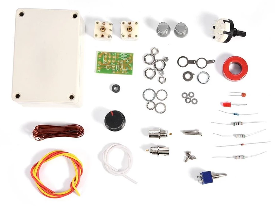
In China you can get a kit for an antenna tuner for about 10 €, which I once assembled for fun. Here is the link to buy it: Manuel Antenna Tuner DIY Kit 1-3 0 MHz
The build was a little tricky because there wasn’t much room in the case. In addition to the parts included in the kit, I added two banana sockets. This is what my finished kit looks like.
Matching the antennas actually works quite well: tested from 160m to 12m.
DL4ZAO has further developed and modified the circuit of the Mini-Whip antenna and published a number of variants. Here you can find the website of DL4ZAO: dl4zao.de
DL4ZAO BlueWhip MegaWhip
I have rebuilt the MegaWhip from DL4ZAO. The reception is much less sensitive to interference compared to the Mini-Whip from pa0rdt. Link to the building instruction: https://www.dl4zao.de/_downloads/Megawhip.pdf
Features of the BlueWhip MegaWhip
It is an active receiving antenna that cannot transmit
The antenna is very broadband and you can easily overlook several mHz with the SDR
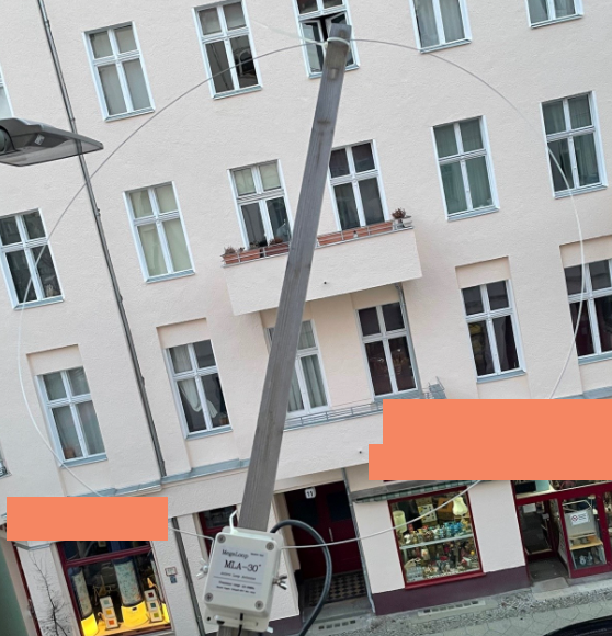
Since I live in the middle of Berlin and am surrounded by 6-story apartment buildings, my reception conditions are very poor. The sources of interference are extremely diverse. In addition, there is an LED street light directly in front of my balcony.
I have provisionally set up the MLA 30 Plus on the balcony on the second floor, on a two-meter high bar, which points diagonally to the street. I have noticed that the further the antenna is from the apartment, the better the reception.
Receiving on 40m
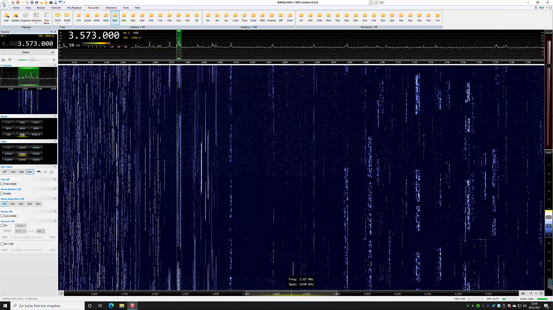
Receiving on 80m
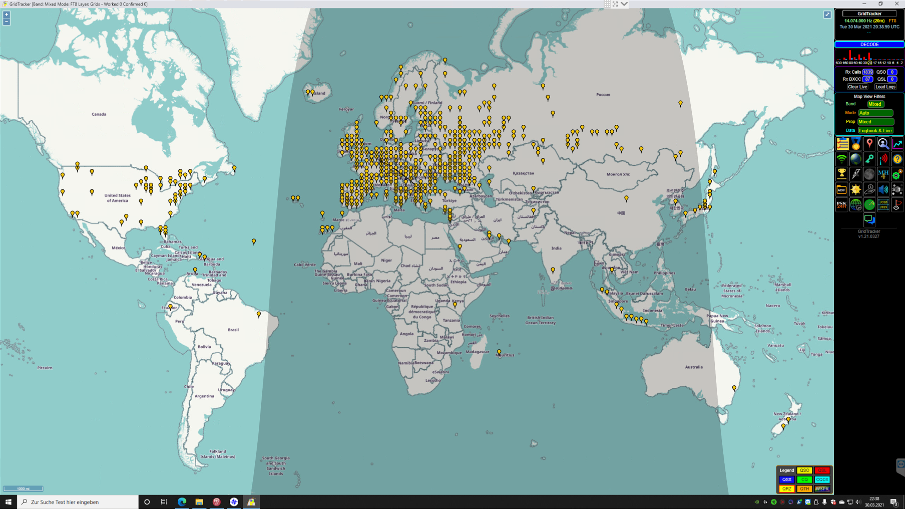
Reception on 20m with FT8 over 2 hours
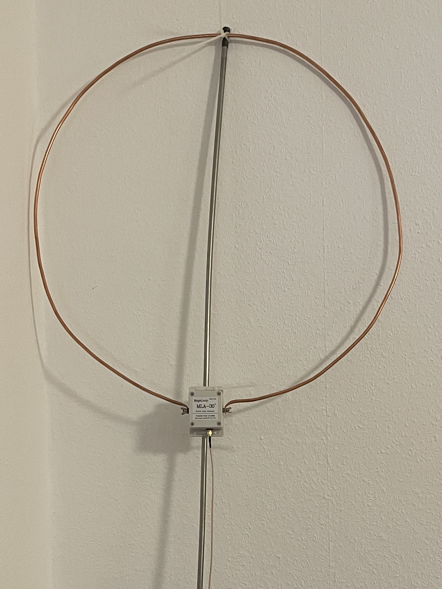
Currently I am working on a modification of the MLA 30 Plus: I have a 2m long copper tube, with 6mm diameter bent into a circle and mounted on the antenna. Provisionally, I have insulated the upper end of the stainless steel rod with self-welding tape and attached the MLA 30 Plus, with cable ties to these. This will later become the final mounting on the balcony.
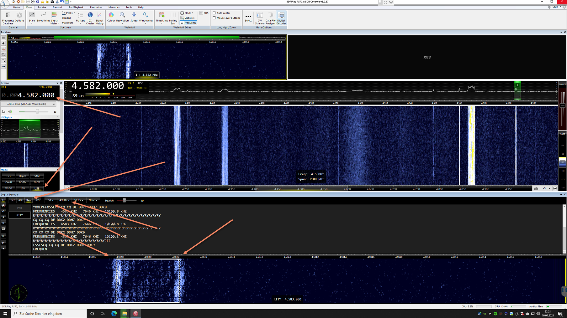
Since version 3.0.4 the SDR console comes with a decoder for the digital modes RTTY and PSK. However, the digital decoder must first be activated or displayed.
Show Digital Decoder and configuration
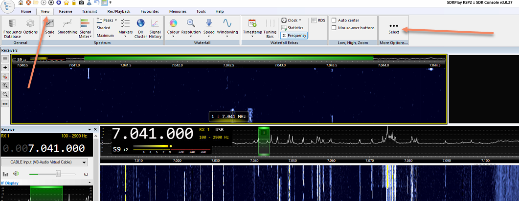
In the SDR console, under the “View” tab on the far right, click on the “Select” button.
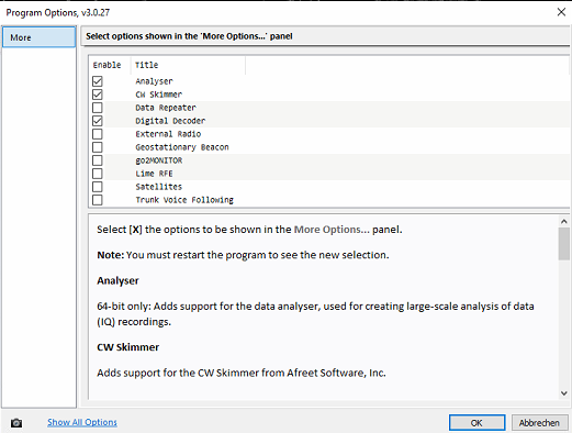
I have activated the “Analyzer”, “CW Skimmer” and the “Digital Decoder”.
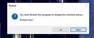
Now the SDCConsole must be restarted once.
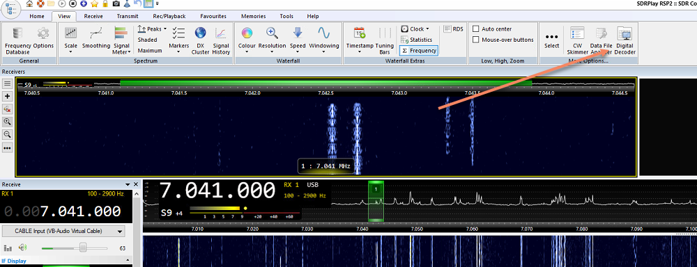
Now the new buttons are available in the “View” tab and with a click on “Digital Decoder”, this is displayed. I have docked the window at the bottom of the SDR console.
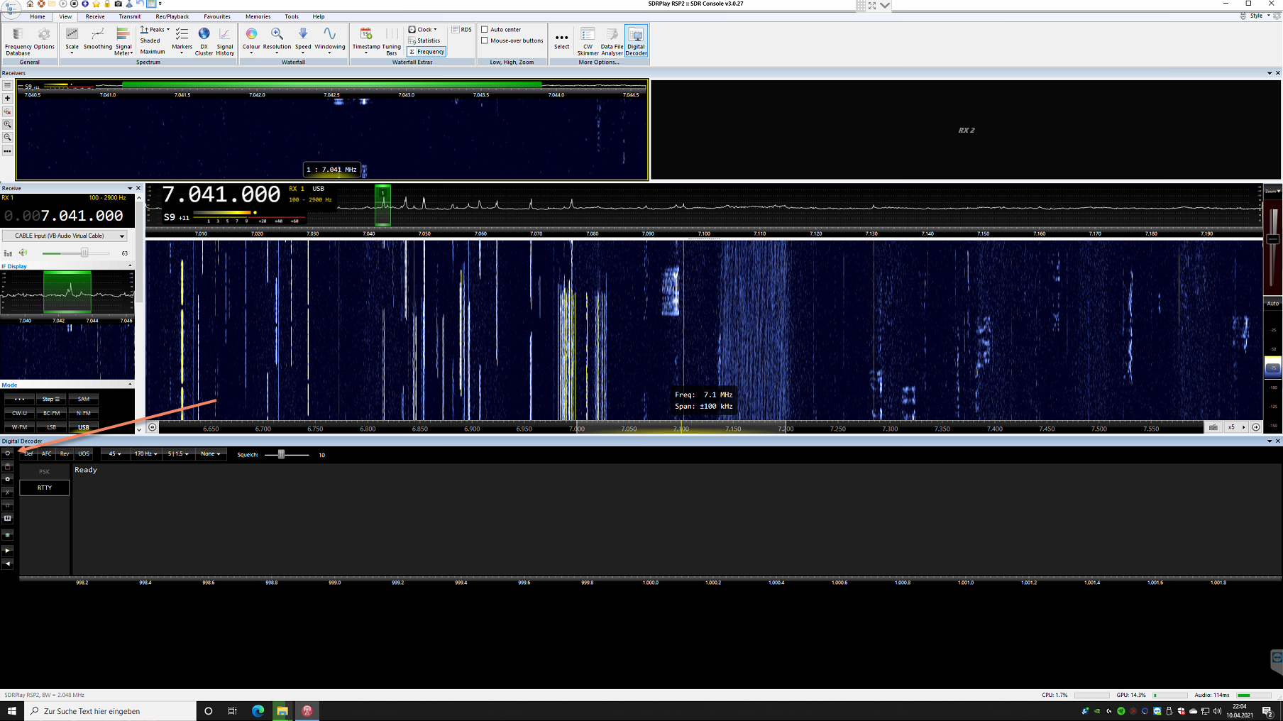
Now the digital decoder must be activated. With a click on the button with the round circle, as marked on the picture, this is activated.
As modes I have selected USB. Sometimes LSB is also used, but this does not have to be changed, because in the digital decoder, as marked, you can also switch on a reverse mode.
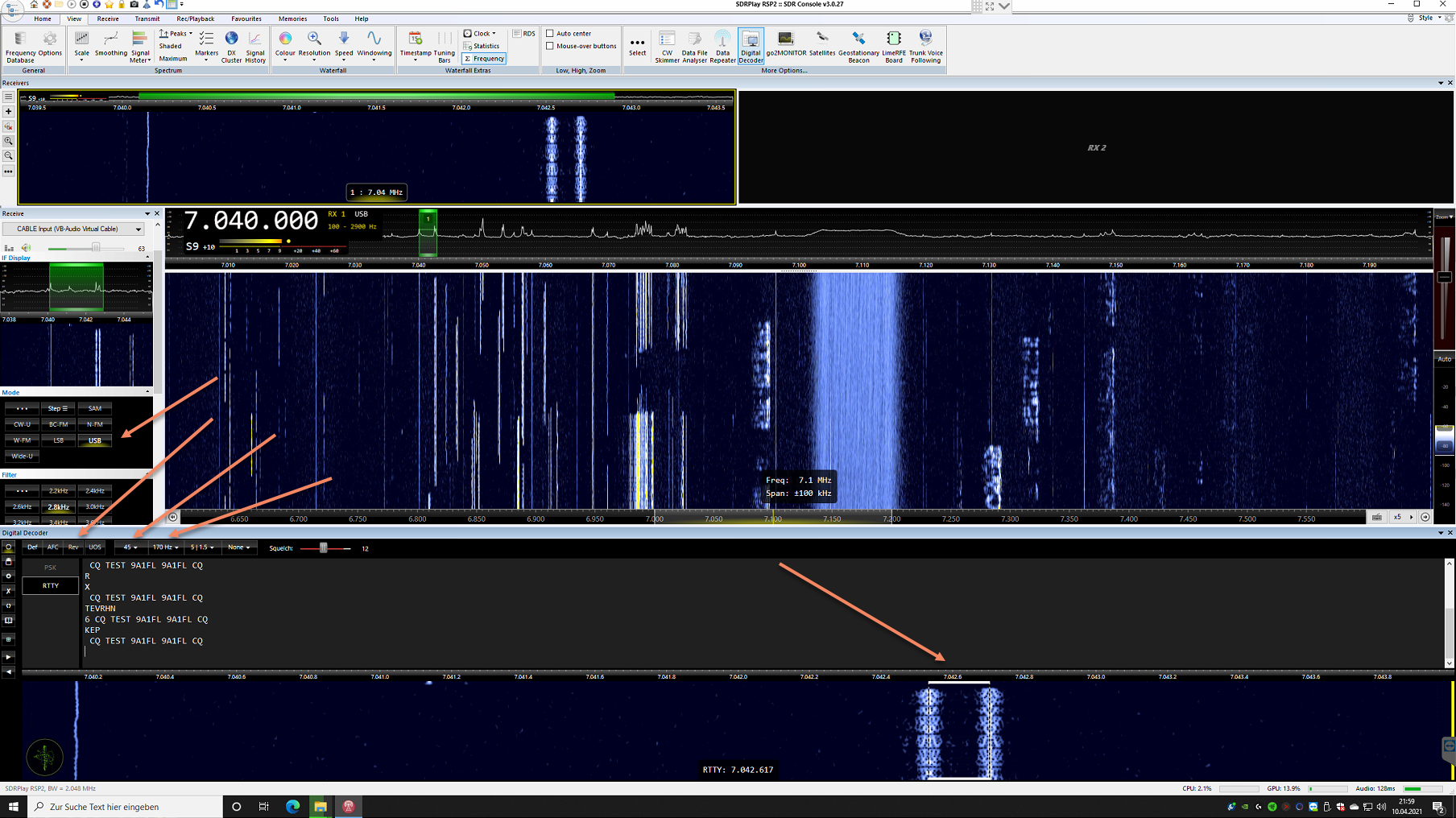
In addition, the speed and the bandwidth must be selected. On 40m I decoded most of the signals with the following settings:
Speed: 45
Bandwith: 170
The bandwidth must be set so that the marking lies exactly on the two end lines of the signal. If in doubt, simply try out several bandwidths until it fits.
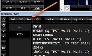
If there is still no readable result, switch on the reverse mode once, if the transmission is on LSB.
Lastly, two optimizations can be made: AFC and Squelch
I have always deactivated AFC. The squelch can be adjusted to the strength of the signal so that no noise is decoded between the transmissions. I then move the slider just before the strength of the emission, which is marked in red.
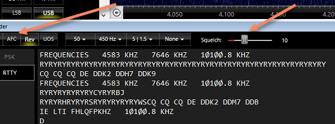
Decode German Weather Service (DWD) on 4.482.5 mHz
To decode the RTTY transmission from the German Weather Service on 4.482.5 mHz, the following settings must be made:
Modulation: USB
Reverse Mode: on
Speed: 50
Bandwith: 450
Set the selection at the bottom of the digital decoder to the two sides of the transmission
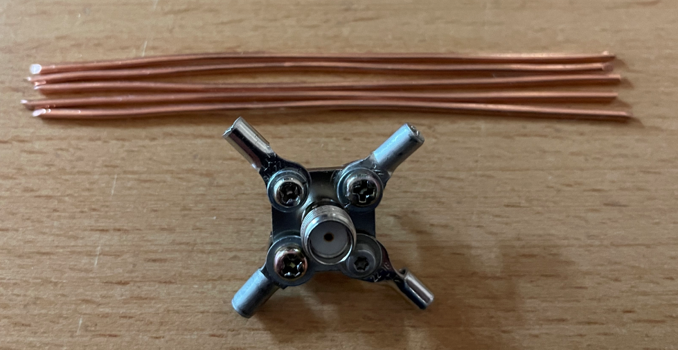
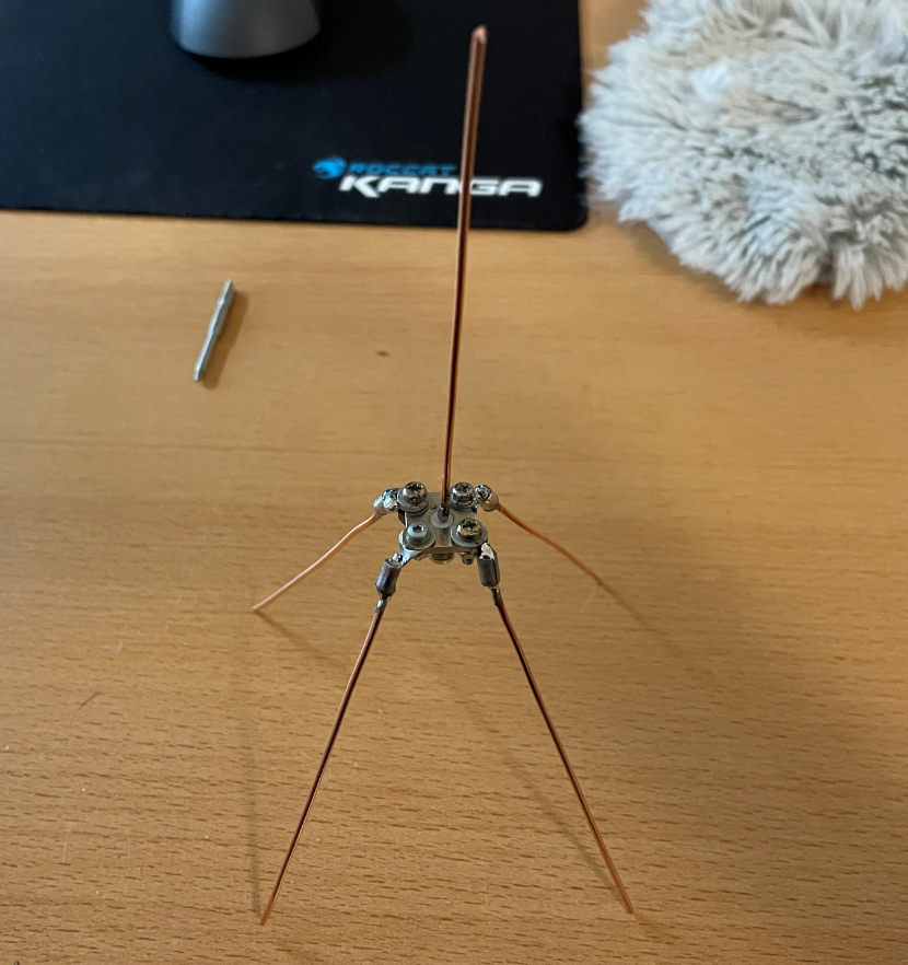
ADS-B for receiving the flight data is on 1090 MHz. So a quarter wavelength is about 6.8 cm. However, I cut my copper wires a little longer so that I can still tune afterwards.
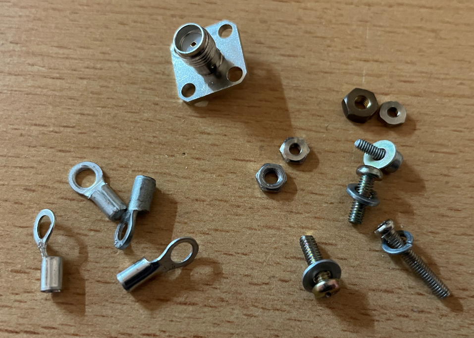
What do you need:
A socket,perhaps a PL, BNC or SMA
Rigid copper wire, 5 x 8 cm (I stripped mine from a 3 core power cable).
optional are cable lugs and screws (instead you can solder the copper wires directly to the socket)
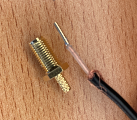
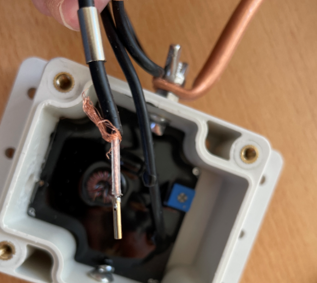
I have decided for the SMA socket, because I want to go later anyway on SMA. Otherwise, I have found four different screws and nuts, in the same diameter.
Next, I attached the cable lugs to the SMA socket with the screws. Alternatively, you can solder the copper wires directly to the socket.
Then I stripped 5 chum wires from a power cable and shortened them to 8 cm.
Then I wetted all the copper wires with tin.
Next, I soldered four copper wires to the lugs.
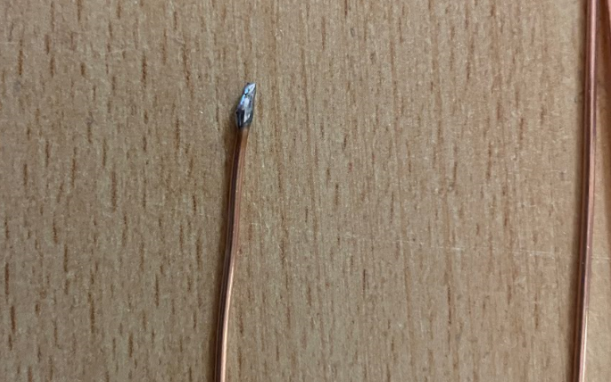
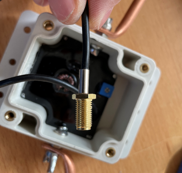
After that I soldered the fifth copper wire to the inner conductor of the SMA socket.
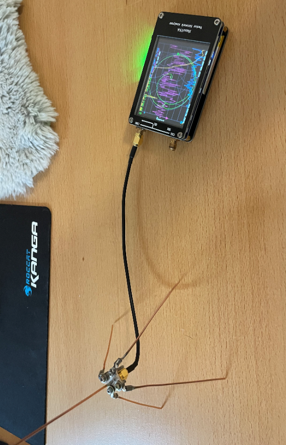
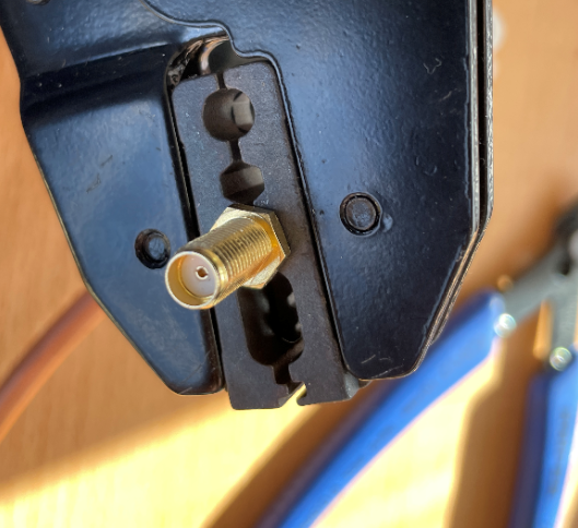
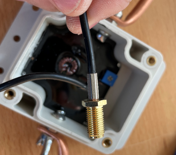
Finally, I connected the antenna to an analyzer and found that the copper wires were too long.
I shortened all copper wires to 6.7 cm and had a SWR of 1:21 on 1090 MHz. I measured including the cable lugs.
The antenna is located in the middle of Berlin on the balcony on the second floor and has a range of about 280 km.
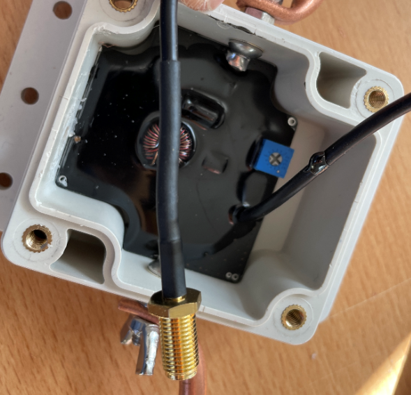
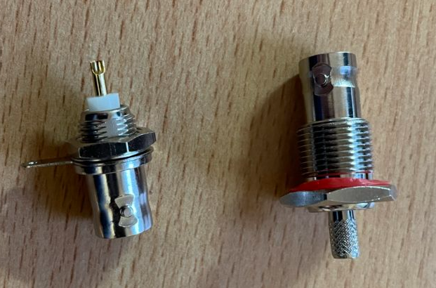
Since the cable on the MLA 30 Plus is fixed, quite thin and 5m long, I decided to install a BNC socket. I had these two BNC sockets in stock. I would have liked the larger with the rubber verbau, but the diameter seemed too thick, so I have the left variant use.
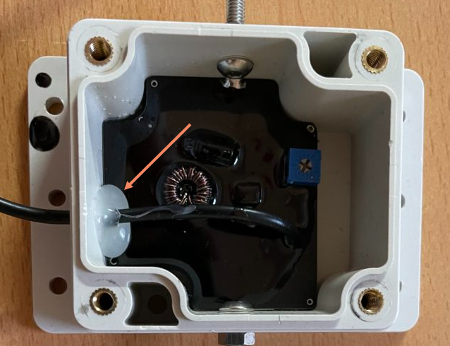
When you open the lid, you will see the cable, which is attached to the housing with hot glue.
The cable can be pulled 20 cm inwards with a little force and then the cable can be clipped off and the adhesive carefully removed.
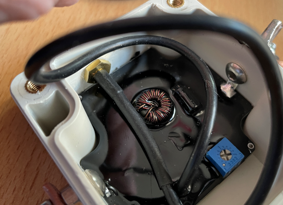
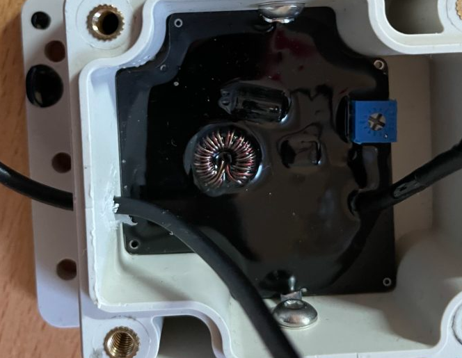
Now the hole can be drilled out. I did this with a hand drill, because otherwise you can hit the coil in the middle very quickly. I have seen some videos where the coil was striped with the drill.
In my case, the diameter of the smaller BNC socket was 9 mm.
Then the rubber must be removed a few cm. After that I bent the screen backwards.
Twist the shield together and tin it.
Tin inner conductor.
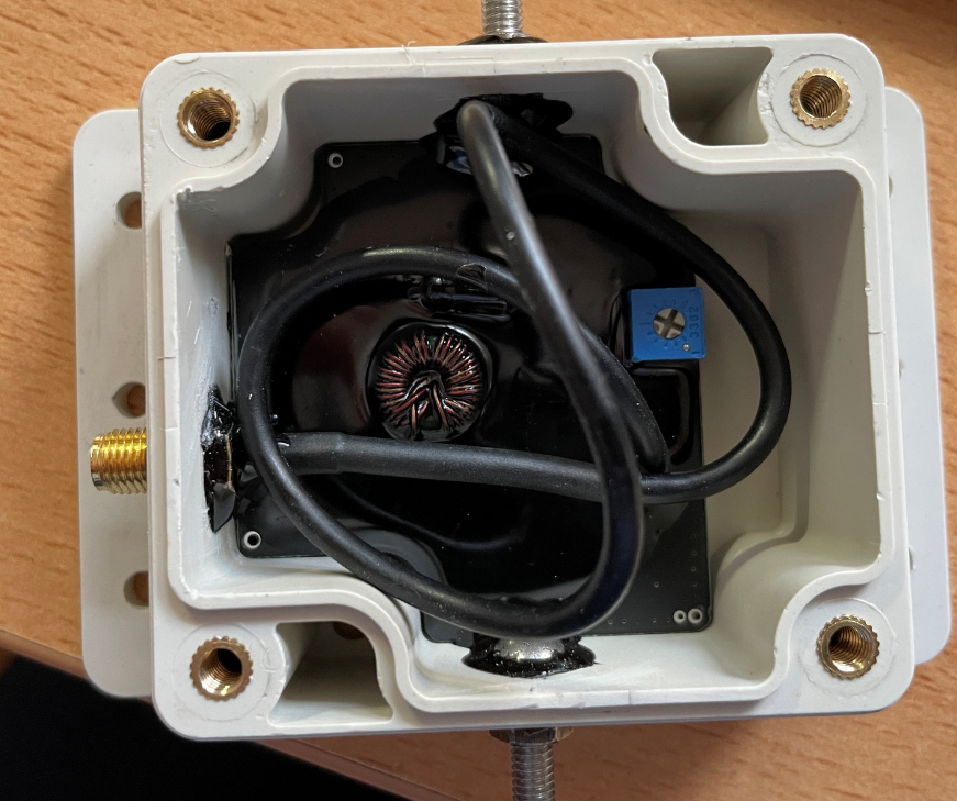
Install the BNC socket. Depending on how much black epoxy was poured, it may be very tight with the nut. It may be necessary to scrape or file the black epoxy down to the board.
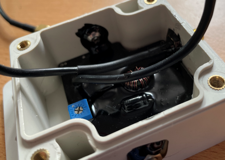
Solder the sheath and inner conductor to the socket. I left the cable longer on purpose in case I want to make adjustments in the future.
If you still have a ferrite core / folding ferrite, you can still attach it to the coax cable in the housing.
It might make sense to adjust the blue potentiometer in the upper left corner. With the included wire loop, you can definitely raise the sensitivity a bit. In my case, I had to turn it counterclockwise.
If you use a longer or thicker loop, you should reduce the sensitivity, otherwise too much interference will be amplified.
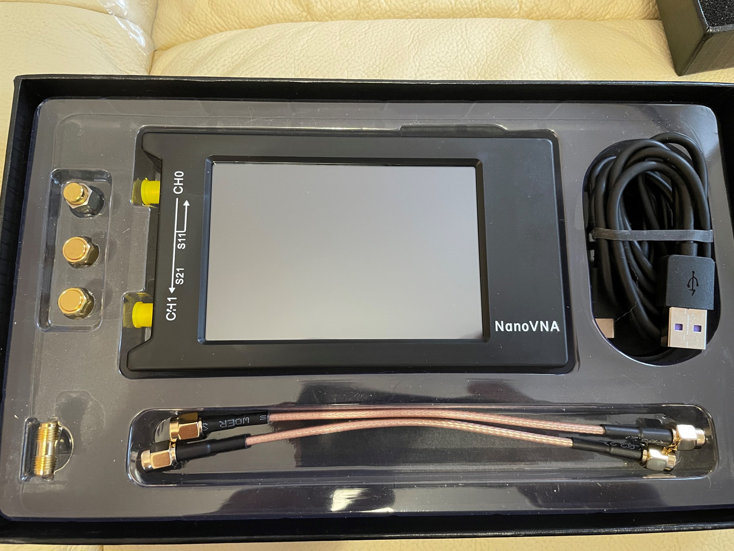
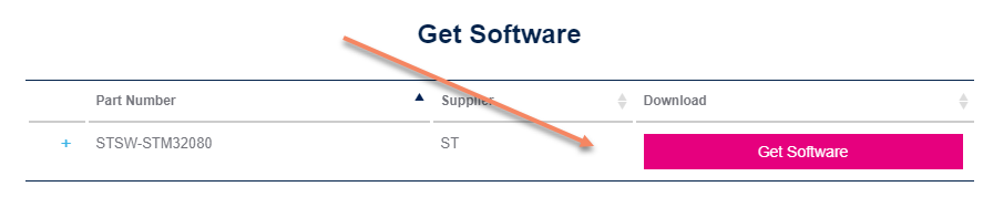
Today the NanoVNA H / H4 came to me and the first thing I did was to update the firmware. How this works, you can read here. Among other things, you can now cover up to 2 GHz.
By clicking on “Get Software”, you can then register and will receive the download link by e-mail.
NanoVNA H / H4 Firmware
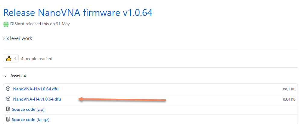
Now you have to download the firmware. You can find it on Github under the following Link DiSLord NanoVNA: DiSLord NanoVNA-H4 Firmware
Make sure to select the correct version, depending on whether you have the H or H4 variant. The wrong firmware makes the device unusable for the time being. You can still write the firmware directly on the chip, but you will need the appropriate hardware.
At the time of this post, version 1.0.64 was current. Here you need to download the file with the extension .dfu:
NanoVNA H / H4 in DFU mode and install driver
First, the NanoVNA H4 must be set to DFU mode: To do this, press the joystick in the middle and switch on the device. The screen should now remain black.
With the NanoVNA H, the DFU mode is started via the Config Menu.
Now the NanoVNA H4 can be connected to the computer via USB. Probably the USB driver is missing in the Device Manager.
Then the driver must be installed in the device manager from the DFU installation path via the device manager. You can find it here: C:\Program Files (x86)\STMicroelectronics\Software\DfuSe v3.0.6\Bin\Driver\Win10
Now DfuSeDemo can be started from the start menu.
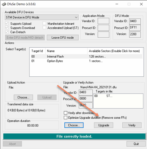
Firmware Flash with DfuSE
In the DfuSE, the lower “Choose Button” must then be clicked:
Now the just downloaded firmware file can be selected:
With a click on “Upgrade” the firmware is now updated:
Please make sure to select the correct firmware. If you flash the firmware without H4 on a NanoVNA H4, the device is defective for the time being. You can still write the firmware directly on the chip, but then you need the appropriate hardware.