Category: DIY

Malahit DSP2 – 2 x 18650 with BMS guide

The Malahit DSP2 has no internal protection, because the current is very low. I installed a BMS for a protection, because i want to protect the Malahit DSP2 for defective 18650 cells. Even if you want to make a mod with 2 18650 cells, it´s would be a good idea.

The Malahit DSP1 / DSP2 is using the TP4056 charging controller, with this specifications:

  • charging current: 0,9 A
  • input voltage: 4,5 V – 5,5 V
  • charging end voltage: 4,2 V

You can charge 2 x 18650 cells in parallel conenction with this controller, but i takes twice as long as before.

What are the features of a BMS?

  • overcharge charge voltage protection (for Li-Ion mostly 4,25 V with + – 0,05 V)
  • undercharge voltage protection (for Li-Ion mostly 2,5 V)
  • maximum continuous current (more MOS, more current)
  • overcurrent detection (short circuit too)
  • reverse protection
  • and some more

Which kind of BMS do you need?

You need a BMS with the specifications:

  • 1S (for parallel connection)
  • For Li-Ion (only with that, the BMS have the correct overcharge, undercharge, etc. specifications)
  • Current with 2 A is more than enough for the Malahit DSP1 / DSP2

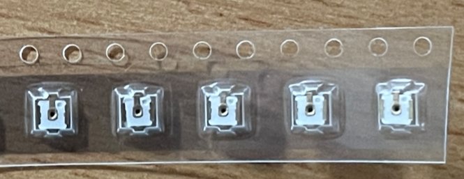
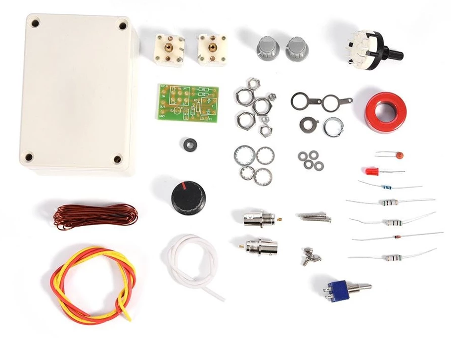
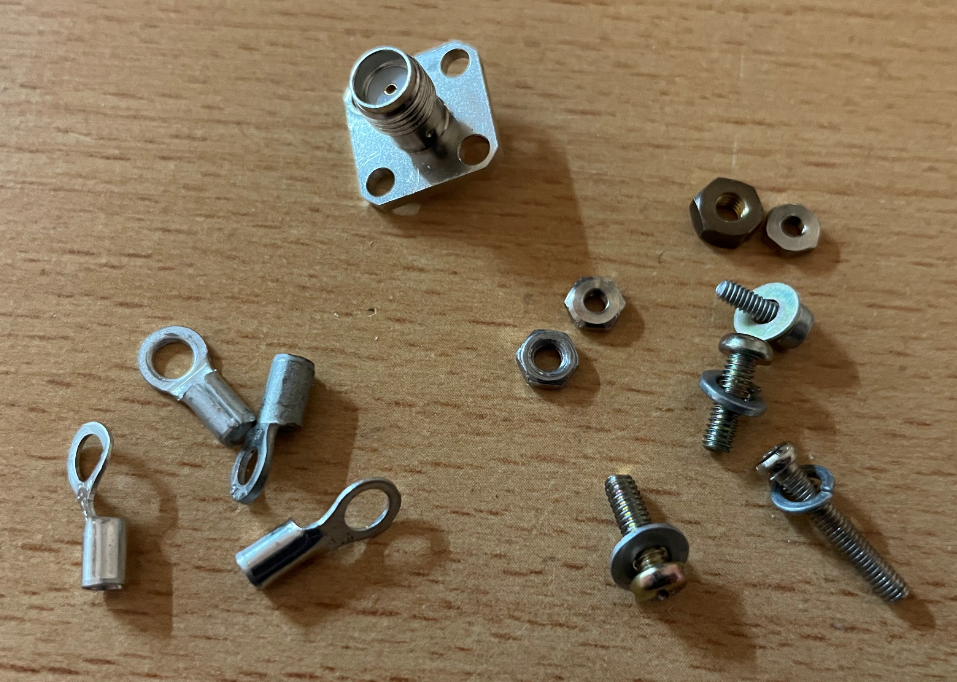
What kind of 2 x 18650 cell holder do you need?

You need a cell holder with this specifications:

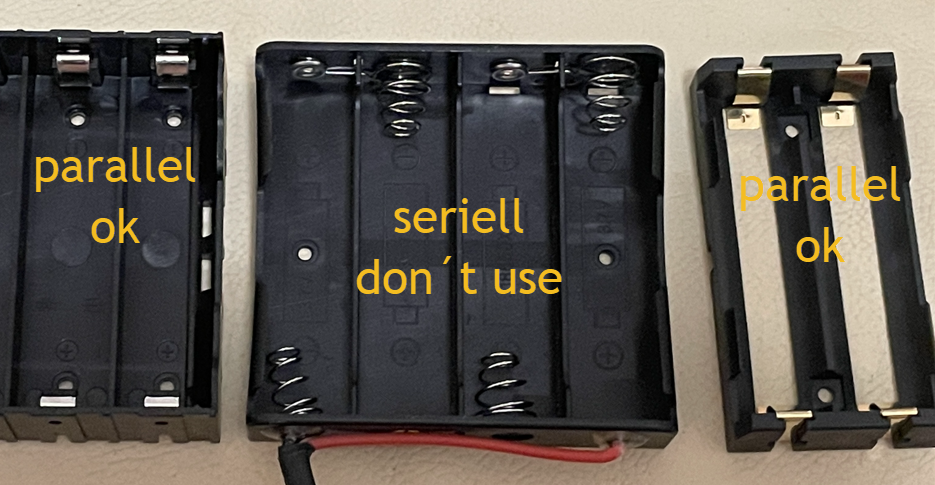
  • Use a cell holder, which is not much longer and heigher, than the 18650 cell. All cell holders on the pictures are ok from the size for the Malahit DSP2
  • Use a parallel cell holder, both cells must be in the same direction. A seriell cell holder have two diffrent directions of the cells, like the holder in the middle. The cell holders on the left and right must be soldered parallel first, because they have no connections between the cells.
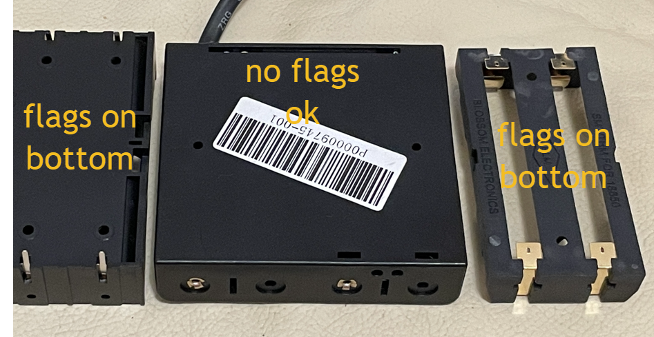
  • No soldering flags outside at the bottom and at the side. For the cell holder left and right, you have to shorten the soldering flags on the bottom, that they can´t reach the Malahit case

1S BMS soldering diagram

Here you can see a diagram of a standard 1S BMS for a Li-Ion cell:

  • B+ / B- to the 18650 cell or cells
  • P+ / P- to the cable of the Malahit DSP2

How to install the BMS in the Malahit DSP2

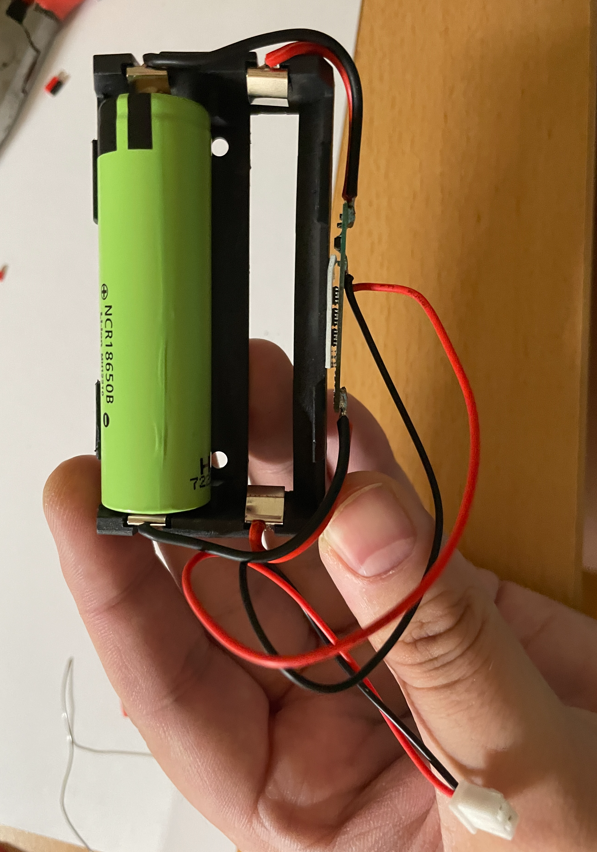
This is a 2 x 18650 cell holder (a 1 x 18650 cell holder is possible too), with a simple 1S BMS. The BMS can be glued with the other side to the holder.

Pay attention to the soldering flags that stick out at the bottom and sides of some battery holders. If they can be connected to the case of the Malahit, you have to shorten them before. If the cells are shorten with the case, only the BMS can safe you from degasing,

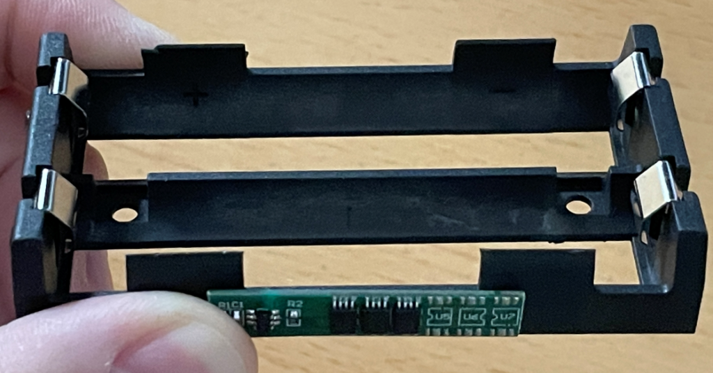
The battery holder has no connections between the cells, this is the reason why i used 2 wires from each site to the B- / B+ sodlering flags. Most holders have only 1 wire, because they hab connections between the cells already soldered.

  • B+ / B- to the 18650 cell or cells
  • P+ / P- to the cable of the Malahit DSP2

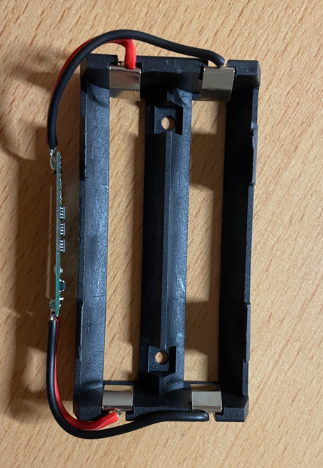
Top view without connection to Malahit:

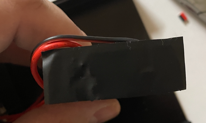
Another view from the top, glued with a tape and connection wires soldered to the Malahit DSP2:

Take care that the sides of the cell holder have no connection to the case. The easy solution is to use isolation tape, but i glued it with epoxy before.

I had to move the speaker to the left and set the cell holder so near it is possible to the speaker. Another solution can be, to glue the cell holder horizontally in the case.

I is a good idea to isolate the contacts on the BMS. Simle with isolation tape or use Epoxy. I used both, but forget to make pictures of the epoxy.

If you use 2 x 18650 cells

At first: The TP4056 charging controller of the Malahit can charge 2 x 18650 cells at the same time, if you use them parallel. But if you want to use 2 x 18650 cells, you have to know some thing.

  • Only use parallel connection (if you use a seriell connection, the voltage adds up with every cell and whith that, the Malahit DSP1 / DSP2 is not compatible)
  • Only use cells from the same type, if the cell have to much difference, it can be dangerous
  • If you want to be on the safe side, measure the internal resistance of the cells and using 2 cells, with almost the same internal resistance

At the first time of use, charge the two cells to the end, before you put them in the cell holder (if not the balancing current can be very high and harms the cells or the Malahit)

Where to buy the parts?

I use the smaller 2 x 18650 cell holder and the 5A 1S Li-Ion BMS:

Malahit DSP2 – Mods which are in work

Currently I am working on some mods for the Malahit DSP2. But before I recommend something concrete, I would like to do tests with different variant to really find the best components.

Bluetooth

In the moment i make some tests with Bluetooth boards. The left one is working from 3v to 5,5v and is perfect for the 18650 cell. The little right one has the lesses interferences.

Here you can buy it

BNC Socket

I found a very good BNC socket, which is only a bit bigger than the SMA socket. The other BNC jacks I’ve had were extremely large in circumference, which would have meant that the hole for the jack would no longer stay on one side of the Malahit DSP2’s case. The new socket solves the problem and is still high quality.

Only the hole for the socket must be a little bit bigger. With the U.FL port the rest is no problem and plug and play.

Here you can buy it, the item on the right: https://de.aliexpress.com/item/1005001950793102.html

SMA Sockets

I make some test with other SMA to U.FL connectors. Some of them are making much interferences. The right one is the best one. All have the same diameter and can fit into the SMA socket hole of the Malahit DSP2.

BMS and 2 x 18650 cells

At the moment i test some 18650 cell holder and BMS. I already use a external BMS and 2 x 18650 cells in my Malahit DSP2. Also there are many cell holder ons the market. Some of them can fit protected 18650 cells and some of them not.

Here is the guide how to do the mod and how to buy: http://mini-whip.de/2021/09/15/malahit-dsp2-bms-install-uide/

U.FL Sockets

At some time i thought my U.FL socket is broken. But than i found, that the U.FL port on the SMA cable was broken. If the U.FL bushing does not survive the experiments, I can replace it.

When i finished, i create guides for all of the mods.

Malahit DSP2 – Holder from Serhii PSB

Serhii PSB built a very very nice Holder for the Malahit DSP1 / Malahit DSP2. You can find his Youtube channel here: Serhii Youtube channel

Features

  • Two versions for Malahit DSP1 and Malahit DSP2 (only original)
  • 2 mm stainless steel
  • addditional surface treatment
  • cutouts at the rear for increased speaker clarity
  • protective pads so that the Malahit DSP1 / DSP2 does not slip or vibrate
  • It’s possible to get a custom text engraved as standard. The names of the Malahit developers are engraved as standard

How you can buy it from him:

  • E mail to Serhii PSB ukrsp154@gmail.com or Telegram to “PSB Serg” in english or russian (Please note that he answer in russian, but it´s now problem to translate it with DeepL)
  • Tell him Malahit DSP1 or Malahit DSP2
  • The price with shipping is in the moment about 35 € because it´s a small batch
  • You can sent the momey with Wester Union or SWIFT bank transfer (He sent it from Ukrain, there is no Paypal)
  • Sent him your full address with country and your mobile phone number

Payment with Western Union (very easy):

You can register a new account for Western Union and it´s very easy and takes only 1 minute. You can sent the money from your bank account or with many other options, to Western Union.

  • There are three options to sent money with Western Union, use the option cash
  • You need only his full name and his telephone number and the coutry Ukraine
  • I had to pay a charging fee from 1,90 € for Western Union
  • After that, sent him the transaction number, than he can go to Western Union an get the money

Paypment with SWIFT bank transfer

A SWIFT bank transfer is more difficult, because you need much of data:

  • Go to your online banking and click on foreign bank transfer
  • You get two IBAN numbers from Serhii: One for $ and one for , please use the correct one
  • Serhii tells you the data which you need like:
    • Serhii: Name, full address
    • Serhii bank: Name, full address, SWIFT code
    • Maybe: Intermediary bank: Name, full address, SWIFT code

I sent him a little bit more money with Western Union, because it is a very nice project and i want to support projects like this.

Here can you see the difference between the Malahit DSP1 and Malahit DSP2 stands:

DIY Antenna Tuner 1 – 30 MHz

In China you can get a kit for an antenna tuner for about 10 €, which I once assembled for fun. Here is the link to buy it: Manuel Antenna Tuner DIY Kit 1-3 0 MHz

The build was a little tricky because there wasn’t much room in the case. In addition to the parts included in the kit, I added two banana sockets. This is what my finished kit looks like.

Matching the antennas actually works quite well: tested from 160m to 12m.

SDRConsole – Digital Decoder (PSK / RTTY)

Since version 3.0.4 the SDR console comes with a decoder for the digital modes RTTY and PSK. However, the digital decoder must first be activated or displayed.

Show Digital Decoder and configuration

In the SDR console, under the “View” tab on the far right, click on the “Select” button.

I have activated the “Analyzer”, “CW Skimmer” and the “Digital Decoder”.

Now the SDCConsole must be restarted once.

Now the new buttons are available in the “View” tab and with a click on “Digital Decoder”, this is displayed. I have docked the window at the bottom of the SDR console.

Now the digital decoder must be activated. With a click on the button with the round circle, as marked on the picture, this is activated.

As modes I have selected USB. Sometimes LSB is also used, but this does not have to be changed, because in the digital decoder, as marked, you can also switch on a reverse mode.

In addition, the speed and the bandwidth must be selected. On 40m I decoded most of the signals with the following settings:

  • Speed: 45
  • Bandwith: 170

The bandwidth must be set so that the marking lies exactly on the two end lines of the signal. If in doubt, simply try out several bandwidths until it fits.

If there is still no readable result, switch on the reverse mode once, if the transmission is on LSB.

Lastly, two optimizations can be made: AFC and Squelch

I have always deactivated AFC. The squelch can be adjusted to the strength of the signal so that no noise is decoded between the transmissions. I then move the slider just before the strength of the emission, which is marked in red.

Decode German Weather Service (DWD) on 4.482.5 mHz

To decode the RTTY transmission from the German Weather Service on 4.482.5 mHz, the following settings must be made:

  • Modulation: USB
  • Reverse Mode: on
  • Speed: 50
  • Bandwith: 450
  • Set the selection at the bottom of the digital decoder to the two sides of the transmission

ADS-B – Groundplane Antenna DIY

ADS-B for receiving the flight data is on 1090 MHz. So a quarter wavelength is about 6.8 cm. However, I cut my copper wires a little longer so that I can still tune afterwards.

What do you need:

  • A socket,perhaps a PL, BNC or SMA
  • Rigid copper wire, 5 x 8 cm (I stripped mine from a 3 core power cable).
  • optional are cable lugs and screws (instead you can solder the copper wires directly to the socket)

I have decided for the SMA socket, because I want to go later anyway on SMA. Otherwise, I have found four different screws and nuts, in the same diameter.

  • Next, I attached the cable lugs to the SMA socket with the screws. Alternatively, you can solder the copper wires directly to the socket.
  • Then I stripped 5 chum wires from a power cable and shortened them to 8 cm.
  • Then I wetted all the copper wires with tin.
  • Next, I soldered four copper wires to the lugs.
  • After that I soldered the fifth copper wire to the inner conductor of the SMA socket.
  • Finally, I connected the antenna to an analyzer and found that the copper wires were too long.
  • I shortened all copper wires to 6.7 cm and had a SWR of 1:21 on 1090 MHz. I measured including the cable lugs.
  • The antenna is located in the middle of Berlin on the balcony on the second floor and has a range of about 280 km.

MLA 30 Plus – SMA socket

I’ll skip the first steps, because I had already described them in the instructions for the BNC socket. You can read that here: http://mini-whip.de/2021/04/08/mla-30-plus-bnc-buchse/

  • I stripped the cable a few cm, almost as long as the SMA socket is.
  • Now I have bent the outer conductor backwards.
  • Then I soldered the inner conductor.
  • Since I decided to use the crimp variant of the SMA socket, I now have to pull the heat shrink tubing and crimp sleeve onto the cable
  • Now the inner conductor can be inserted.
  • Next, the outer conductor must be bent forward again and the crimp sleeve put on.
  • Now the connector can be crimped.
  • The whole thing should then look like this.
  • Finally, I pulled a heat shrink tube over the connection.
  • It should then look like this.
  • Finally I glued the bushing and the screws for the loop with epoxy.
  • Before that, I roughened the areas with a file so that the epoxy would sit better.
  • The last thing to do is to fold the cable and close the lid.
  • I left the cable extra longer in case I still want to make adjustments.

MLA 30 Plus – BNC socket

Since the cable on the MLA 30 Plus is fixed, quite thin and 5m long, I decided to install a BNC socket. I had these two BNC sockets in stock. I would have liked the larger with the rubber verbau, but the diameter seemed too thick, so I have the left variant use.

  • When you open the lid, you will see the cable, which is attached to the housing with hot glue.
  • The cable can be pulled 20 cm inwards with a little force and then the cable can be clipped off and the adhesive carefully removed.
  • Now the hole can be drilled out. I did this with a hand drill, because otherwise you can hit the coil in the middle very quickly. I have seen some videos where the coil was striped with the drill.
  • In my case, the diameter of the smaller BNC socket was 9 mm.
  • Then the rubber must be removed a few cm. After that I bent the screen backwards.
  • Twist the shield together and tin it.
  • Tin inner conductor.
  • Install the BNC socket. Depending on how much black epoxy was poured, it may be very tight with the nut. It may be necessary to scrape or file the black epoxy down to the board.
  • Solder the sheath and inner conductor to the socket. I left the cable longer on purpose in case I want to make adjustments in the future.
  • If you still have a ferrite core / folding ferrite, you can still attach it to the coax cable in the housing.
  • It might make sense to adjust the blue potentiometer in the upper left corner. With the included wire loop, you can definitely raise the sensitivity a bit. In my case, I had to turn it counterclockwise.
  • If you use a longer or thicker loop, you should reduce the sensitivity, otherwise too much interference will be amplified.