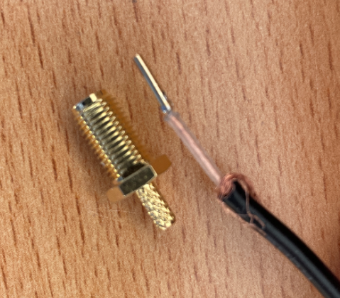
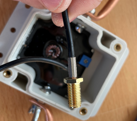
Since the cable on the MLA 30 Plus is fixed, quite thin and 5m long, I decided to install a BNC socket. I had these two BNC sockets in stock. I would have liked the larger with the rubber verbau, but the diameter seemed too thick, so I have the left variant use.
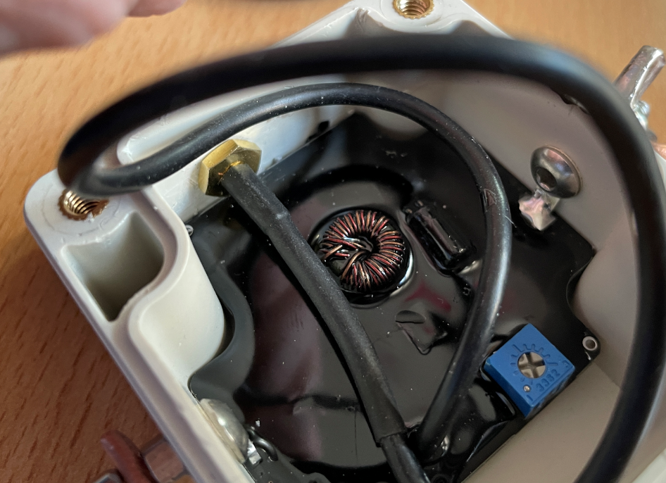
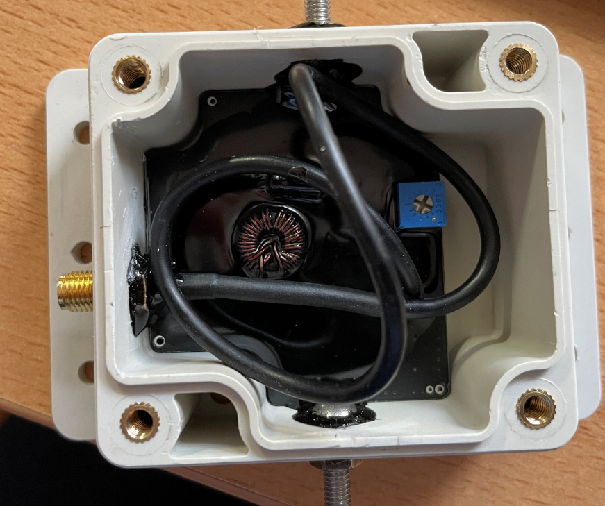
When you open the lid, you will see the cable, which is attached to the housing with hot glue.
The cable can be pulled 20 cm inwards with a little force and then the cable can be clipped off and the adhesive carefully removed.
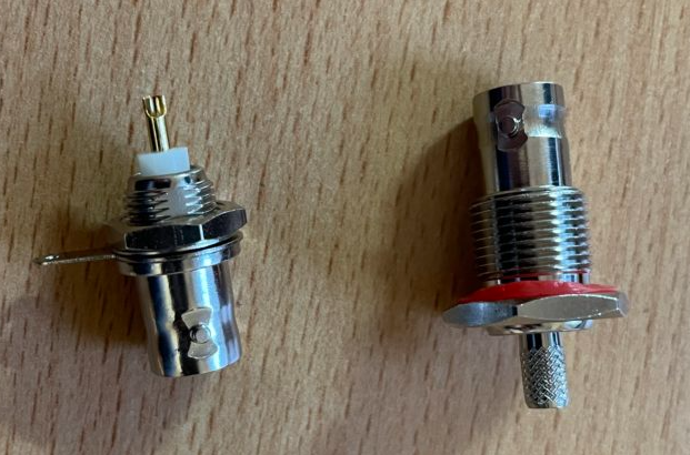
Now the hole can be drilled out. I did this with a hand drill, because otherwise you can hit the coil in the middle very quickly. I have seen some videos where the coil was striped with the drill.
In my case, the diameter of the smaller BNC socket was 9 mm.
Then the rubber must be removed a few cm. After that I bent the screen backwards.
Twist the shield together and tin it.
Tin inner conductor.
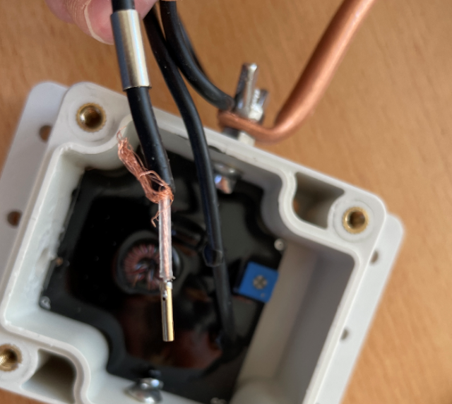
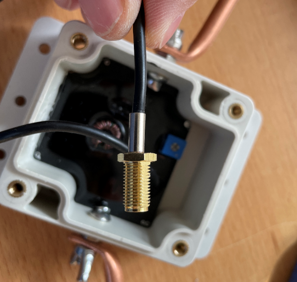
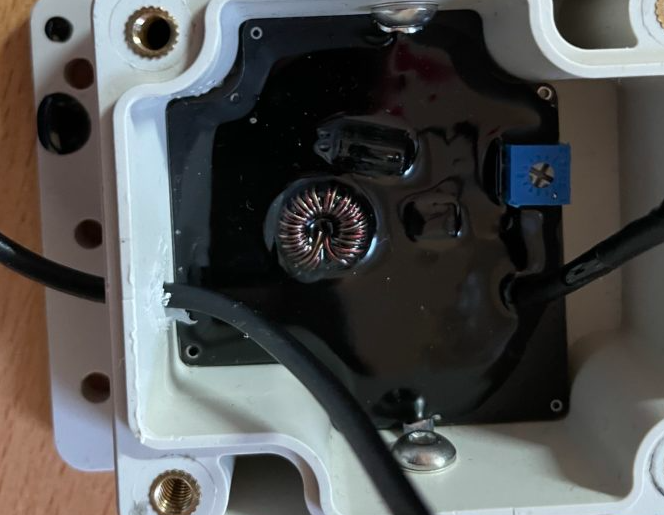
Install the BNC socket. Depending on how much black epoxy was poured, it may be very tight with the nut. It may be necessary to scrape or file the black epoxy down to the board.
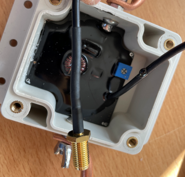
Solder the sheath and inner conductor to the socket. I left the cable longer on purpose in case I want to make adjustments in the future.
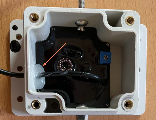
If you still have a ferrite core / folding ferrite, you can still attach it to the coax cable in the housing.
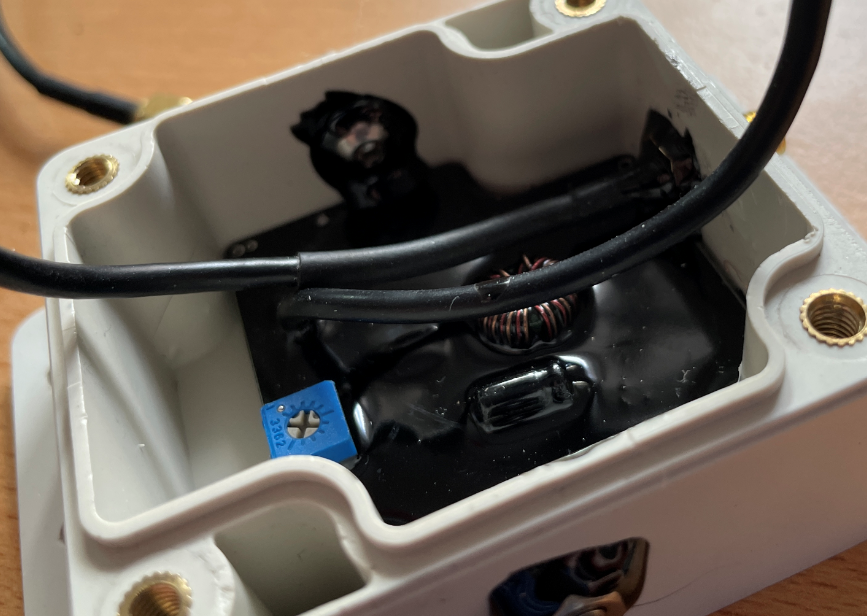
It might make sense to adjust the blue potentiometer in the upper left corner. With the included wire loop, you can definitely raise the sensitivity a bit. In my case, I had to turn it counterclockwise.
If you use a longer or thicker loop, you should reduce the sensitivity, otherwise too much interference will be amplified.
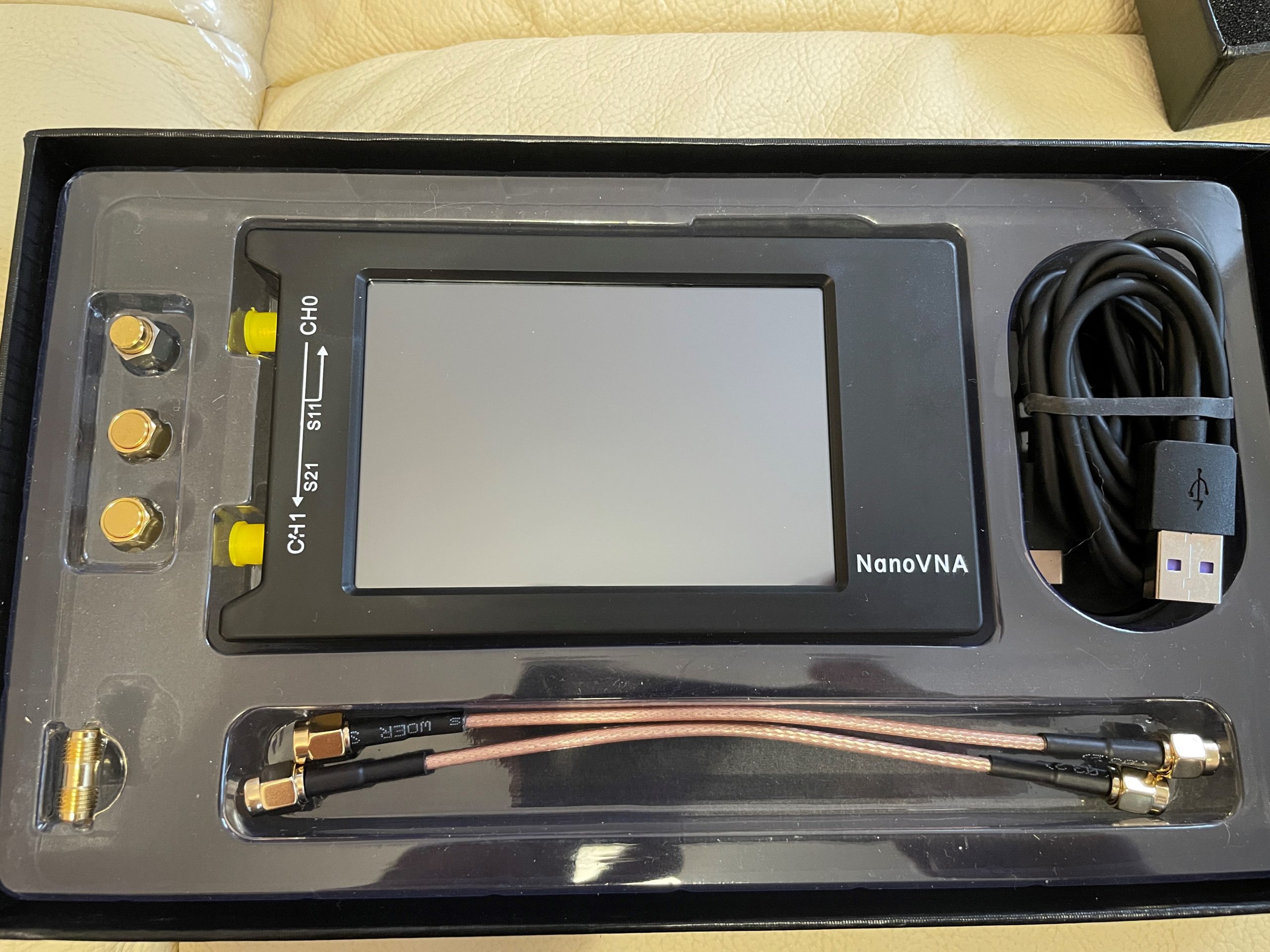
Today the NanoVNA H / H4 came to me and the first thing I did was to update the firmware. How this works, you can read here. Among other things, you can now cover up to 2 GHz.
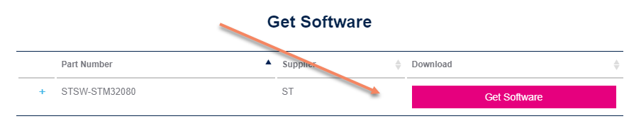
By clicking on “Get Software”, you can then register and will receive the download link by e-mail.
NanoVNA H / H4 Firmware
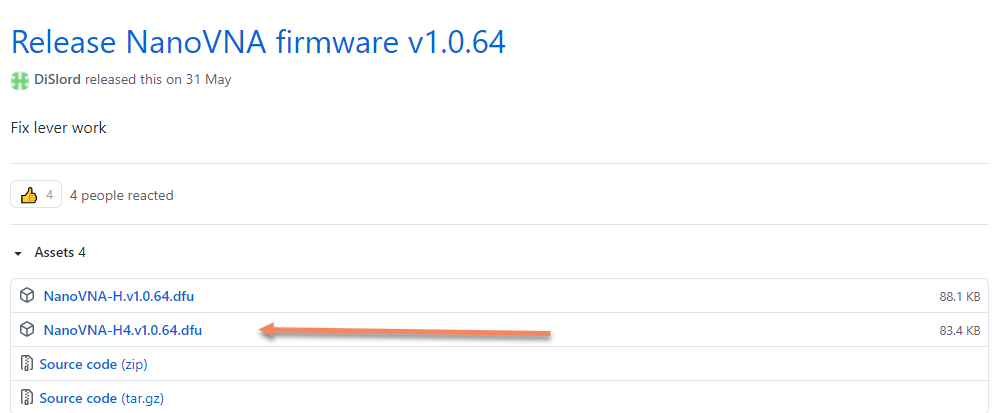
Now you have to download the firmware. You can find it on Github under the following Link DiSLord NanoVNA: DiSLord NanoVNA-H4 Firmware
Make sure to select the correct version, depending on whether you have the H or H4 variant. The wrong firmware makes the device unusable for the time being. You can still write the firmware directly on the chip, but you will need the appropriate hardware.
At the time of this post, version 1.0.64 was current. Here you need to download the file with the extension .dfu:
NanoVNA H / H4 in DFU mode and install driver
First, the NanoVNA H4 must be set to DFU mode: To do this, press the joystick in the middle and switch on the device. The screen should now remain black.
With the NanoVNA H, the DFU mode is started via the Config Menu.
Now the NanoVNA H4 can be connected to the computer via USB. Probably the USB driver is missing in the Device Manager.
Then the driver must be installed in the device manager from the DFU installation path via the device manager. You can find it here: C:\Program Files (x86)\STMicroelectronics\Software\DfuSe v3.0.6\Bin\Driver\Win10
Now DfuSeDemo can be started from the start menu.
Firmware Flash with DfuSE
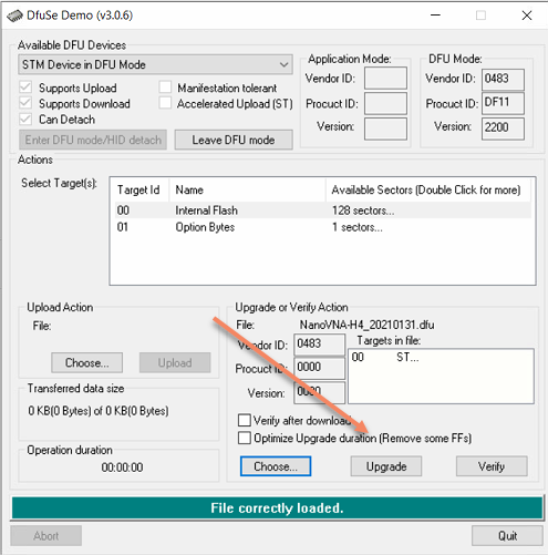
In the DfuSE, the lower “Choose Button” must then be clicked:
Now the just downloaded firmware file can be selected:
With a click on “Upgrade” the firmware is now updated:
Please make sure to select the correct firmware. If you flash the firmware without H4 on a NanoVNA H4, the device is defective for the time being. You can still write the firmware directly on the chip, but then you need the appropriate hardware.